
This is a simple, step-by-step example of vector statics as applied to a simple truss (which you can see at the top of the page.) It illustrates the concepts of analysing a simple, three-dimensional truss using vector statics. We’ll also look at both the cross and dot products of two vectors.
Background

The Special Products Division of Vulcan Iron Works Inc. produced many interesting fabricated structures for the marine industry, including a yard yacht crane, the Construction Assistance Vehicle, and work for Perry Submarine. The origins of this particular project are lost in obscurity, but the drawing you see above was prepared for Capt. Robert J. North, twin brother of Jim North (right,) who was on the crew of the family yachts. (His son Robert Jr. also worked at the SPD.) There is no indication as to who drew it up or how it was designed except that it’s origin was on a “PGA Napkin.” Based on the drawing, it was probably meant to be mounted on the bed of a pick-up truck or something slightly larger. No capacity for the rig is given, neither are there any calculations to go with the drawing. Our task is to figure out what kinds of loads and ultimately stresses there were for a given load. We will do this with the following assumptions:
- The supports act as “ball and socket” types, meaning that they are capable of transmitting forces in three directions but no moments (three degrees of freedom.)
- The struts act as truss members, capable of transmitting axial forces but no bending.
- The load acts at Point 4 (the intersection of the three struts,) as utilising the telescoping boom point would introduce bending into the calculations.
A Brief Overview of Cartesian Vectors
These equations will be related to the drawing in the next section, along with the variables. The general equation for a Cartesian vector is the following:

The scalar length of that vector is

Let us define a unit vector (a vector with a scalar length of 1) as follows:

The direction cosines (the cosines of the angles of the three Cartesian directions to the Cartesian axes) are

and these direction cosines must obey the law

The unit vector can be expressed thus:

With all of this, the Cartesian vector can also be formulated as follows:

Calculating Forces, Moments and Reactions
Most statics textbooks present problems in some kind of 3D view (isometric or perspective.) In this case we have a straight up, three-view drawing of the structure, which makes getting the numbers off of the drawing easier (due to the dimensions) but requires us to pay attention to details like the fact that joints 1,2 and 3 are offset from the x-axis (bed of the truck.) In spite of the uncertain origins of this project, it’s drawn in a proper right-handed view scheme, which make presentation of the right-handed coordinate system simple.
In any case from Equation (2) the lengths of the struts are as follows (based on the dimensions given on the drawing):


These can be compared to those on the drawing. Vectors, as we know, can apply to forces and positions. The position vectors from the supports 1,2 and 3 to the meeting point 4 (Equation (1)) are


The unit position vector for Strut 1 (Equation (3)) is

and the direction cosines (Equation (4)) are

The angles (in degrees) are thus

Note that this is a two-dimensional strut. Direction cosines are normally associated with three-dimensional objects but that doesn’t have to be the case. In like fashion the unit position vector, direction cosines and angles for Strut 2 are


and for Strut 3


Since these are struts and the forces are co-linear with the axes of the struts, the forces in the struts can be defined thus, the product of the unit vectors and the scalar forces:


Note that the scalar forces for Struts 2 and 3 are the same; this is because of symmetry. The force of the weight (which also acts at Point 4, like the forces in Equations (19), (20) and (21)) is

We will leave the weight as an unknown constant. The summation of forces at Point 4 is

Solution With Moments
We will now take moments around Point 1. There is no moment with Force 1 because the moment arm for 1 and the force for 1 are co-linear. The moment of Force 2 with respect to Point 1 is

![\overrightarrow{M_{2}}=\left[\begin{array}{ccc} i & j & k\\ 95 & 80.75 & 0\\ 0.268\,{\it F_{2,3}} & 0.945\,F_{2,3} & 0.186\,{\it F_{2,3}} \end{array}\right] =\left(15.033\,\hat{i}-17.686\,\hat{j}+68.201\,\hat{k}\right)F_{2,3}](https://s0.wp.com/latex.php?latex=%5Coverrightarrow%7BM_%7B2%7D%7D%3D%5Cleft%5B%5Cbegin%7Barray%7D%7Bccc%7D+i+%26+j+%26+k%5C%5C+95+%26+80.75+%26+0%5C%5C+0.268%5C%2C%7B%5Cit+F_%7B2%2C3%7D%7D+%26+0.945%5C%2CF_%7B2%2C3%7D+%26+0.186%5C%2C%7B%5Cit+F_%7B2%2C3%7D%7D+%5Cend%7Barray%7D%5Cright%5D+%3D%5Cleft%2815.033%5C%2C%5Chat%7Bi%7D-17.686%5C%2C%5Chat%7Bj%7D%2B68.201%5C%2C%5Chat%7Bk%7D%5Cright%29F_%7B2%2C3%7D&bg=%23ffffff&fg=%23111111&s=0&c=20201002)
and again in like fashion

![\overrightarrow{M_{3}}=\left[\begin{array}{ccc} i & j & k\\ 95 & 80.75 & 0\\ 0.268\,{\it F_{2,3}} & 0.945\,F_{2,3} & -0.186\,{\it F_{2,3}} \end{array}\right] =\left(-15.033\,\hat{i}+17.686\,\hat{j}+68.201\,\hat{k}\right)F_{2,3}](https://s0.wp.com/latex.php?latex=%5Coverrightarrow%7BM_%7B3%7D%7D%3D%5Cleft%5B%5Cbegin%7Barray%7D%7Bccc%7D+i+%26+j+%26+k%5C%5C+95+%26+80.75+%26+0%5C%5C+0.268%5C%2C%7B%5Cit+F_%7B2%2C3%7D%7D+%26+0.945%5C%2CF_%7B2%2C3%7D+%26+-0.186%5C%2C%7B%5Cit+F_%7B2%2C3%7D%7D+%5Cend%7Barray%7D%5Cright%5D+%3D%5Cleft%28-15.033%5C%2C%5Chat%7Bi%7D%2B17.686%5C%2C%5Chat%7Bj%7D%2B68.201%5C%2C%5Chat%7Bk%7D%5Cright%29F_%7B2%2C3%7D&bg=%23ffffff&fg=%23111111&s=0&c=20201002)
The moment of the weight around Point 4 is

![\overrightarrow{M_{w}}=\left[\begin{array}{ccc} i & j & k\\ 95 & 80.75 & 0\\ 0 & -W & 0 \end{array}\right] =-95\,W\hat{k}](https://s0.wp.com/latex.php?latex=%5Coverrightarrow%7BM_%7Bw%7D%7D%3D%5Cleft%5B%5Cbegin%7Barray%7D%7Bccc%7D+i+%26+j+%26+k%5C%5C+95+%26+80.75+%26+0%5C%5C+0+%26+-W+%26+0+%5Cend%7Barray%7D%5Cright%5D+%3D-95%5C%2CW%5Chat%7Bk%7D&bg=%23ffffff&fg=%23111111&s=0&c=20201002)
Summing moments from Equations (24), (25) and (26) yields

from which we can solve the forces in the side struts to

We substitute this into Equation (23) to obtain

At this point we have an interesting situation. For Equation (29) to be true both the forces in the 


The vector forces are thus


Since the reactions are co-linear with the forces, we also have the reactions. Our assumption (see drawing) for Forces 2 and 3 is correct; the struts are in compression and the reaction is primarily downward. For Force 1 our assumption is wrong and the reaction is tensile.
Solution Without Moments
Although we can use moments to solve the problem, the redundant solution we obtained suggests that using moments is overkill for a problem like this. And this is certainly the case; all of the forces come to a point, and if we make that point our free body diagram, we can obtain the solution.
Let us break up Equation (23) into its two Cartesian components as follows:
.762F1 + .535F2,3 = 0 (32a, x-direction)
.648F1 + 1.891F2,3 – W = 0 (32b, y-direction)
If we multiply Equation (32a) by -0.85,
-.648F1 – .455F2,3 = 0 (33)
Adding Equations (32b) and (33) and solving,
F2,3 = 0.696W (34)
Substituting this into either Equation (32a) or (32b),
F1 = -0.489 W (35)
If we assume W = 1000 lb, then F1 = -489 lb. and F2,3 = 696 lb., which are all the same results we obtained before.
Checking the Results: Finite Element Analysis
It’s good engineering practice to have two ways of checking a result. In this case we’ll use the ANSYS finite element program. Like most FEA programs, ANSYS has plenty of output; we’ll try to “cut to the chase” and only show what’s really necessary. So that the FEA setup matches our assumptions, we’ll use spar elements, which means that only axial loads (and stresses) are considered.
First, the finite element model pictorially. The size of the struts is dictated by the cross-sectional area of the Schedule 40 pipe, which can be found using the Engineering Power Tools program which can be downloaded from this site.
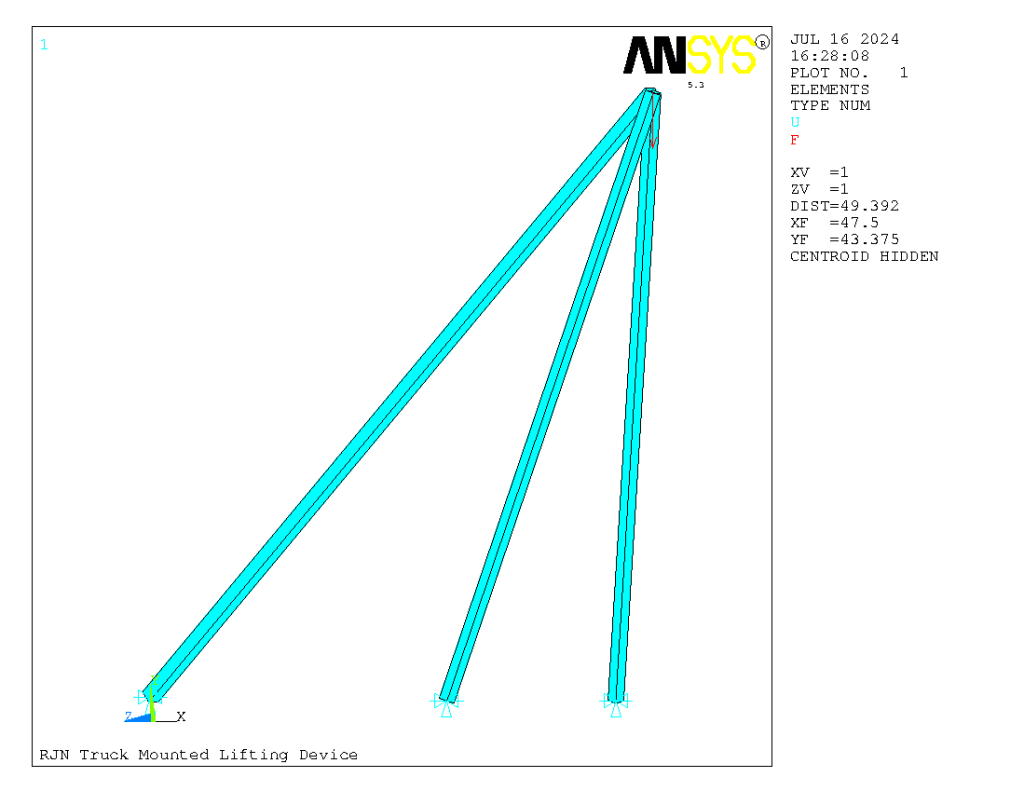
You can see the applied load and the connections. ANSYS rotates the view a little so that you can see the entire model in one view. Since ANSYS prefers actual loads, we will assume a 1000 lb. (1 kip) load at the boom point, which will make comparison with the results from 3D statics relatively simple.
Now we present the axial stresses (AXIAL, psi) and axial loads (MEMFOR, lbs.) on the model.
POST1 ELEMENT TABLE LISTING
STAT CURRENT CURRENT
ELEM  AXIAL  MEMFOR
1    154.14  489.24
2   -312.60 -696.48
3   -312.60 -696.48
Note that ANSYS uses a more sensible sign convention that we did in the problem. Strut 1 is in tension and Struts 2 and 3 are in compression. (At least we lined up the element and strut numbers!)
The stresses are plotted as follows:
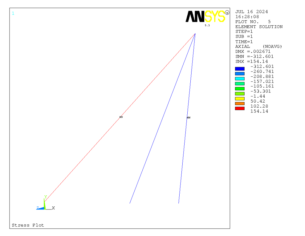
It is easy to see here that the front struts are in compression and the back in tension. The stresses are obtained by simply dividing the strut force by the strut cross-sectional area (since they are spar elements.)
Now we tabulate the nodal loads (the numbering is the same as the “hand” solution:
NODE FX      FY      FZ
1  372.77  316.86
2 -186.39 -658.43 -129.66
3 -186.39 -658.43  129.66
4         1000.0
Again these match those from the solution above. The forces sum to zero, as they should.
Although it is not a result of statics analysis, the deflections from ANSYS are shown below.
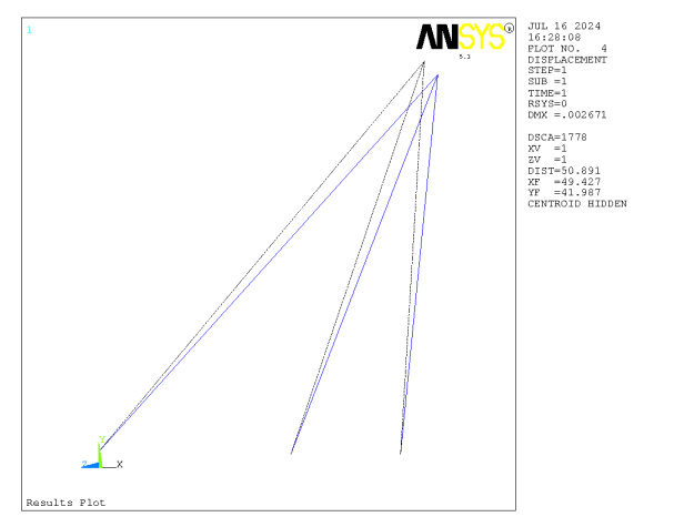
The maximum deflection (at the boom point) is about 0.003″, which is very small. The stresses are likewise small. Even if the load is increased by a factor of ten to 10,000 lbs. (5 U.S. tons) the stresses are still in the reasonable range for structural steels. There are some things to note however:
- The assumption that the struts are truss/spars does not consider the inclusion of bending or column buckling.
- The assumption that the connections are ball and sockets may not be totally realistic either, as inspection of the drawing will show.
- Although we’ve spent our time analysing the structural behaviour and integrity of the system, a more important consideration is that of overturning. The truck may not have enough counterweight to take full advantage of the strength of the struts; it will probably turn over before the struts fail. This is a common problem with equipment such as cranes and excavators.
Dot Product
We can also use this problem to illustrate the dot product of two vectors. First some information on the dot product, from Strelkov:


One use for the dot product is determining the angle between two vectors. Let us determine the angle between vectors 1 and 2 above (the angle between vectors 1 and 3 is the same.) We know the position vectors of 1 and 2, and using the Equation 7.8 above we proceed as follows:
- Left Hand Side: ab = (95)(23)+(80.75)(81.25)+(0)(16) = 8745.9375
- Right Hand Side: ab = (124.68)(85.95) = 10716.246
- Taking the inverse cosine: α = arccos(8745.9375/10716.246) = 35.3 degrees
