This is an expansion of a problem from Targ (1988) on this subject, which comes into play in both Statics and Mechanics of Materials.
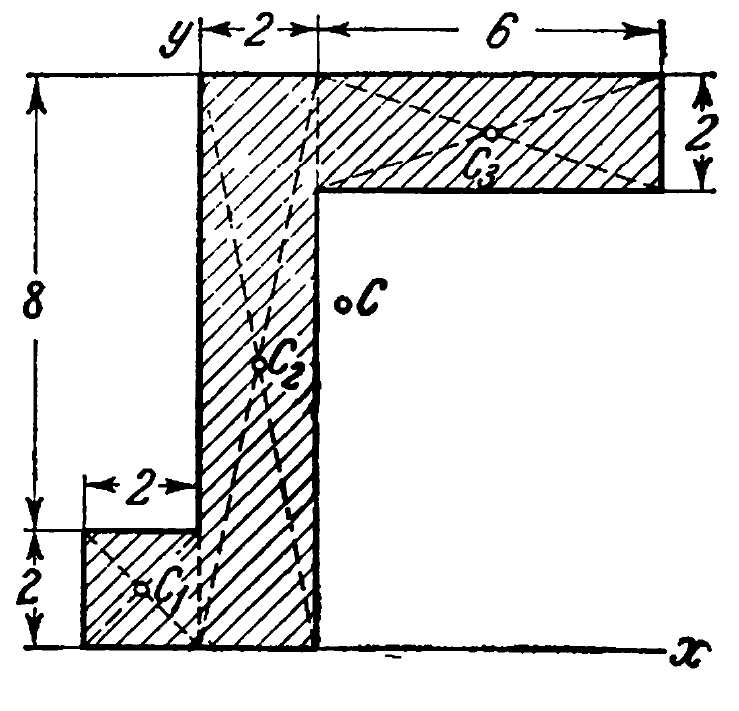
Let us begin by considering the area in question; the dimensions are in centimetres.
The first thing we will do is determine the centroid of the entire system. We do this by determining the centroid of each part of the section and then determining the centroid of the entire system using a weighted average. A similar procedure is employed in Determining the Eccentric Moment, Rotational Inertia and Pendulum Frequency for a Vibratory Eccentric.
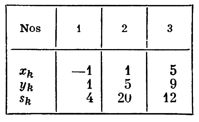
The area and the coordinates of the centroids for each section are noted in the table at the right. Each of these centroids is relative to the coordinate system shown in the diagram above.
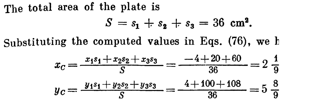
The centroid is determined as follows:
Now we turn to the matter of the moment of inertia. The moment of inertia for a rectangle is given by the equation

But this equation needs to be understood as follows:
- The base b is the side of the rectangle which is parallel to the axis around which the moment of inertia is being taken. So, for Area 2, for Ix, b = 2, as the short side is parallel to the x-axis.
- The height h is the side of the rectangle which is perpendicular to the axis around which the moment of inertia is being taken. So, for Area 2, for Ix, h = 8, as the long side is perpendicular to the x-axis.
- For the moment of inertia Iy, you simply switch b and h.
- The moment of inertia computed with Equation (1) for rectangles is for an axis system with the origin a the centroid of the rectangle. To find the moment of inertia around another point/axis system, you need the parallel axis theorem.
And this is where things get a little tricky. The formulas for this transformation in a Cartesian system is given as follows:


where 


The hard part is understanding why the reversal in Equations (2a) and (2b) between the moments of inertia and values of 
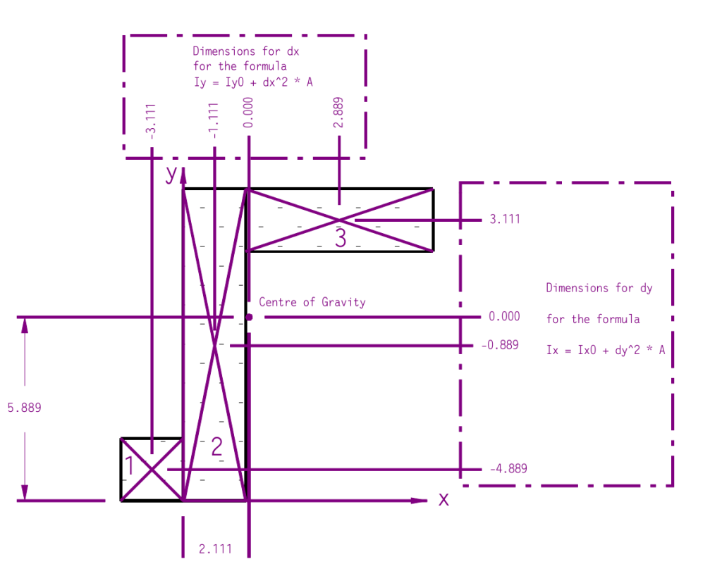
The value Ix means that the moment of inertia is taken around the x-axis, not in the direction of the x-axis. Thus the shifts in coordinates for the x-axis moment of inertia take place in the y-direction and vice versa.
To obtain the result we simply make this transformation for each section and add up the Ix and Iy values that result. This is shown in the table below. The table is split up for formatting purposes.
| Area | b | h | Area Centroid Distance from x-axis, cm | Area Centroid Distance from y-axis, cm | Area Ix Centroid of Section, cm4 | Area Iy Centroid of Section, cm4 |
| 1 | 2 | 2 | 1 | -1 | 1.333 | 1.333 |
| 2 | 2 | 10 | 5 | 1 | 166.667 | 6.667 |
| 3 | 6 | 2 | 9 | 5 | 4.000 | 36.000 |
| Centroid x coordinate | 2.111 | |||||
| Centroid y coordinate | 5.889 |
| Area | Area, cm^2 | dy for Parallel Axis Theorem, cm | dx for Parallel Axis Theorem, cm | Ix of Area around Total Centroid, cm4 | Iy of Area around Total Centroid, cm4 |
| 1 | 4 | -4.889 | -3.111 | 96.938 | 40.049 |
| 2 | 20 | -0.889 | -1.111 | 182.469 | 31.358 |
| 3 | 12 | 3.111 | 2.889 | 120.148 | 136.148 |
| Total Area, cm2 | 36 | Total I, cm4 | 399.556 | 207.556 | |
| Radius of Gyration, cm | 3.331 | 2.401 |
The radius of gyration is simply


