Let us consider the structure shown above. The problem comes from Seely and Ensign. We need to find the reactions at Points A and B, and the tension in the cord.
The tricky part is to determine how to determine the free body diagram. If we include the entire structure, we will a) miss the cord tension and b) run the risk of an indeterminate structure (and certainly one harder to analyse. The simplest way is to use the bar A-B as our free body diagram (which includes the extension to the loading point,) which would give us the two reactions and the cord tension as shown below.

The unit vectors for the reactions are
uA = j (1a)
uB = – cos 50 i + sin 50 j (1b)
uT = i (1c)
The reaction equations are thus:
RA = RAj (2a)
RB = RB(- cos 50 i + sin 50 j) (2b)
T = Ti (2c)
We can now sum forces:
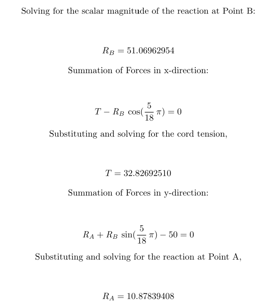
Summation of forces in x-direction: T – RB cos 50 = 0 (3a)
Summation of force in y-direction: RA +RB sin 50 – 50 = 0 (3b)
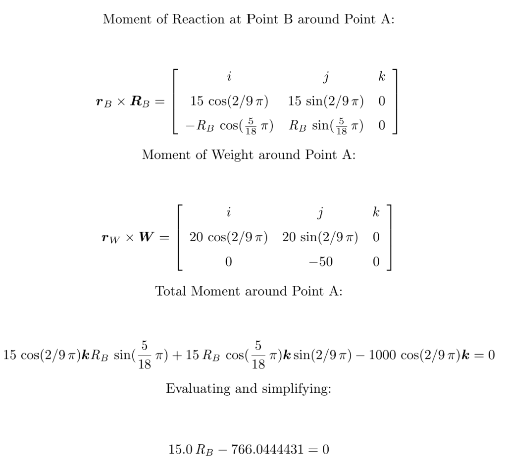
For summation of moments, we take the moments around Point A. This eliminates RA and T from the moment equation. The position vectors of Point B and the point of application of the load have the same unit vector but different lengths. The unit vector is
uAB = cos 40i + sin 40j (4)
And the position vectors are
rAB = 15(cos 40i + sin 40j) (5a)
rAL = 20(cos 40i + sin 40j) (5b)
We turn to our LaTex editor to complete the solution (note that the angles from here on out are in radians):