Ever since people set out to sea in ships, the issues of buoyancy and stability have been of importance. In spite of this, the treatment it receives in textbooks is often lacking. Following is an overview of the subject; basic understanding of the principles is essential in performing the experiment and interpreting the results.
Buoyancy
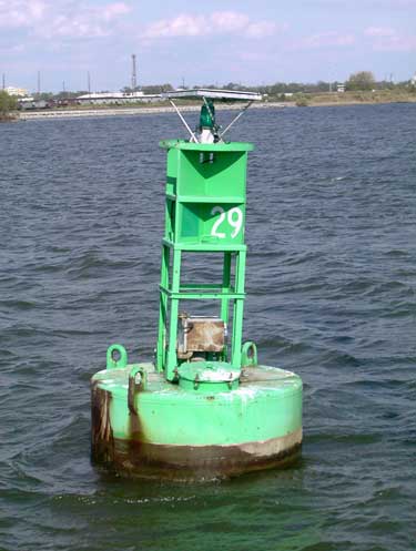
Buoyancy is ultimately what makes things float, such as the buoy above. This is true whether the material the thing that floats is made of is lighter than water (like the balsa wood rafts Thor Heyerdahl and his crew crossed the Pacific with in 1947) or heavier than water. The latter would include objects from the buoy shown to the ships of the U.S. Navy.
The basic concept is very simple: for anything placed in a fluid medium, the upward force the medium exerts on the body is equal to the weight of the fluid the body displaces. This is not only true of bodies placed in water; it is also true of those in air. The difference is that, for those in air, the weight of the air displaced is usually not enough to “float” the aircraft. A notable exception are dirigibles such as the “Goodyear blimp,” which is filled with helium, a gas lighter than air. Another lighter-than-air gas used is hydrogen. This is very combustible, as everyone was reminded of when the Hindenburg caught fire in New Jersey in 1938.
Most buoyancy applications are marine ones, and it is those we will focus our attention. We will also concentrate on rectangular forms and flat-bottomed vessels, which simplifies the math somewhat. However, these principles can be extended to just about any floating craft. Before we start let’s look at a diagram of the physical variables; you’ll need this as you move through the narrative.
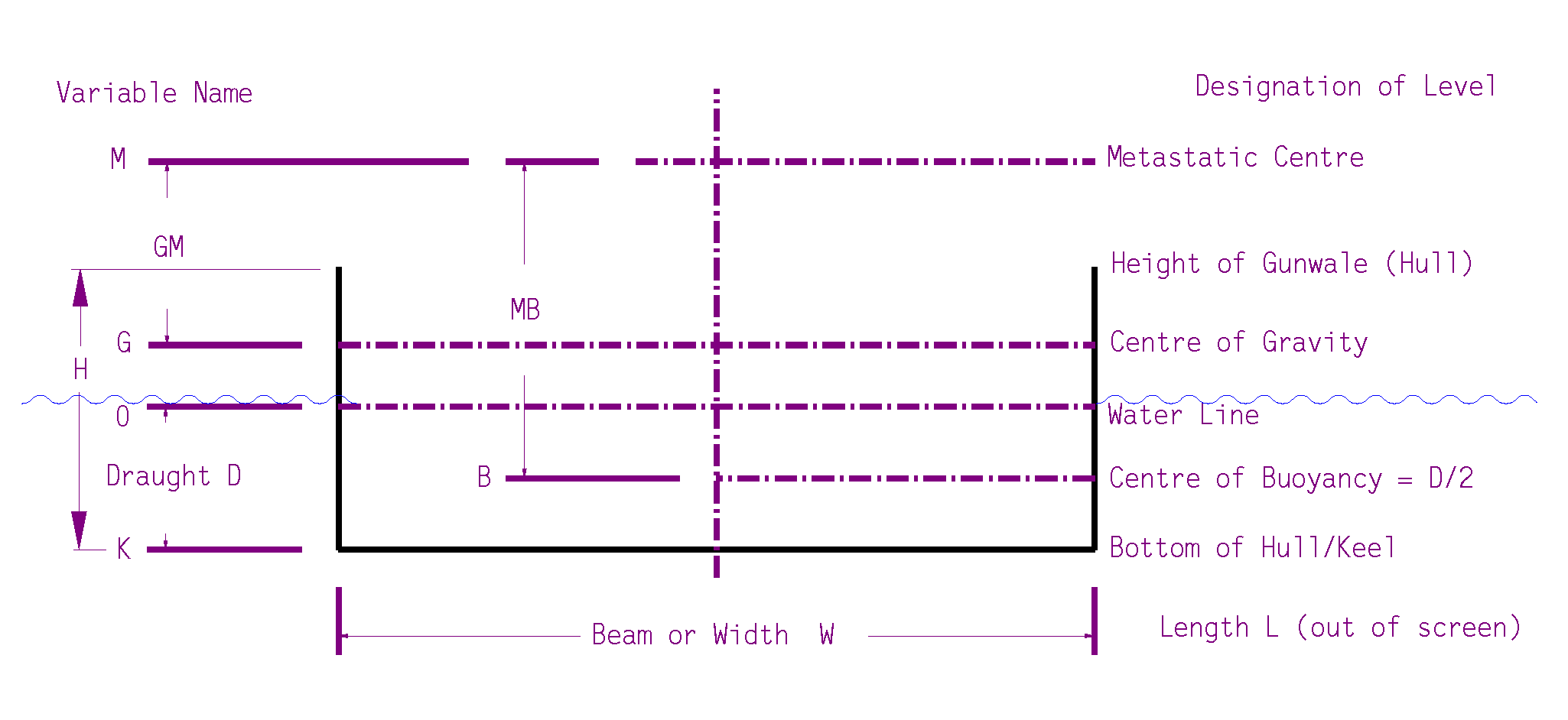
Note that the variable letter designations are on the port (left) and the names are on the starboard (right.) Also note that the use of the term “keel” is a stretch; for a flat-bottomed boat like the one we used in the experiment, it’s OK, but for most ships it’s the “sharp” edge at the very bottom of the hull, which you can see in the photo below.

Consider first the following: how the force of the fluid on the flat hull of a craft varies with depth1:

For a fluid at rest, the hydrostatic pressure increases linearly with depth, thus

where
- p is the hydrostatic pressure
- γ is the unit weight of the water, and
- D is the depth from the water’s surface to the bottommost point of the vessel, usually called the draught.
The table in the figure above is simply Equation (1) illustrated for a series of depths from 1′ to 5′. The unit weight of the water is assumed to be 64 pcf as opposed to the 62.4 pcf we normally assume; that’s because the ship is in salt water, which has a higher unit weight (and which is why objects float higher in salt water than fresh.) As the vessel sinks deeper into the water, the pressure on the bottom of the hull increases linearly with depth, as Equation (1) predicts.
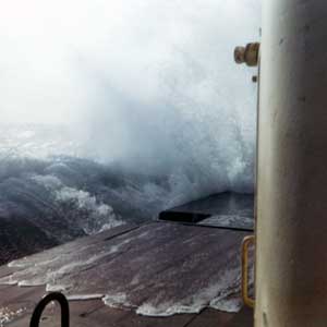
This distance from the water line to the top of the rectangle (the gunwale) is called the freeboard; the results of inadequate freeboard can be seen in Figure 3.
Turning to the displacement, for a vessel of beam (width) W and a length L the volume it displaces is given by the equation

where
- V = volume of water the vessel displaces
- W = width (beam) of the vessel
- L = length of the vessel
The upward buoyant force on the vessel is simply the pressure computed in Equation (1) by the plan area of the ship, thus

where 
Combining this with Equations (1) and (2) yields

Which is the displacement equation we set for to start with.
For the boat to float, it has to be in static equilibrium, and so the downward force of the weight of the boat Wboat must equal the upward force Fbuoyant. Therefore,

So far we’ve established a relationship between the weight of the boat and the volume of water it displaces. In theory the far right hand side of Equation (5) applies only to flat-bottomed boats. In reality it can be shown (with a little calculus, closed form, graphical or numerical) that it applies to any vessel.
What this means is that there are three ways we can weigh an existing boat:
We can simply weigh it on a scale. For small boats this isn’t too difficult; larger ones can be tricky. We can then estimate how far it will sink into the water.
We can measure the freeboard, then obtain D and, knowing L, W and the unit weight of water, we can compute the weight of the boat. This works easily for rectangular boats; for real boats, you have to determine the relationship between the actual waterline and the displacement, then see where the actual waterline ends up.
- We can use an overflow method, which is okay for small experiments (like Archimedes used) but not so hot on a larger scale. But this illustrates our concept.
Procedure for determining volume of water displacement using Archimedes’ principle2:

Consider the tank at the top, which is suspended over a reservoir under it (and with suitable ramps to direct the water to the reservoir.) The tank and the reservoir have the same length so that the L term in Equations (2) and (3) will divide out. The tank at the top is filled to the rim. A square bottomed vessel 3′ wide such as we considered earlier is placed into the tank, and it sinks 1′. Since the tank was filled to the rim, all of the water it displaced flows out of the tank and into the reservoir. The volume of the water in the reservoir is the same as the volume displaced by the vessel in the tank. If the reservoir were weighed (taking the tare of the reservoir out of the computation) the weight of the water in the reservoir is the same as the weight of the vessel.
But all of this is unnecessary if we can determine the volume of water the vessel displaces. Let us say that the ship has a W = 3′, a L = 6′ and D or K = 1′. Let us also stick with the 64 pcf sea water. The volume the ship displaces is V = (3)(6)(1) = 18 cu.ft. (Equation (2).) The weight the ship displaces is (18)(64) = 1152 lbs. (Equation (4).) From Equation (5), this is the same as the weight of the vessel.
As noted earlier, this can be applied to curved hull vessels as well with a little more advanced mathematics. But people have been going to the sea in ships long before calculus was discovered.
Stability
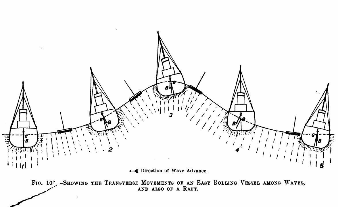
Buoyancy is a fairly straightforward concept, although it may be a little hard to grasp up front. Stability—the ability of the ship to resist overturning—is a little more difficult, although it’s obviously important, as the following diagram of a ship with waves coming at the beam shows3.
Let’s define (or recall) a couple of terms.
Centre of Gravity: this is easy, mathematically this is the centroid of the mass or weight of the ship. An illustration of this is below.
The centre of gravity in a three-dimensional object like a ship is likewise in three dimensions. From bow to stern (lengthwise, in and out of the screen) the CG is obviously located wherever the centre of mass of the ship falls from 0 (stern) to L (bow.) This may seem redundant, but, under normal conditions, the lateral CG is more specific: it must be halfway across the W dimension. If this is not the case, the ship will list (lean to one side or another) and this is not a desirable condition. The vertical CG also falls along the vertical centre of mass; determining this is crucial in finding whether or not a ship is stable while rolling.
In the diagram above, the CG is shown relative to two points: down from the cargo on the deck and upward from the centre of buoyancy. One of the trickiest parts of determining the CG is to establish a reference point from which the CG is measured. One of those is the…
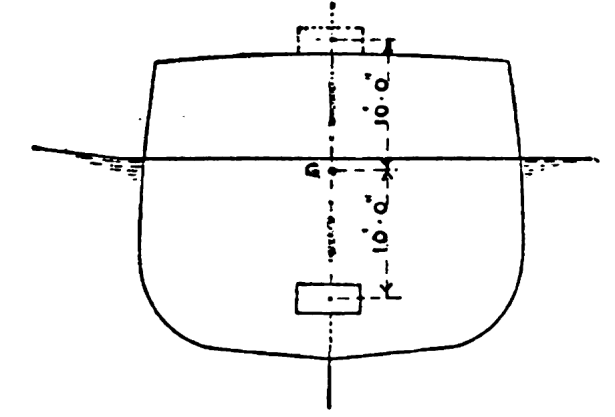
Centre of Buoyancy: this is a little trickier, this is the centroid of the cross-sectional area of the ship under the water line, as shown below.

As you can see, for a box-shaped vessel which is not listing (i.e., leaning at an angle) or has no squat (i.e., not angled along the length of the boat) the centre of buoyancy is located halfway down the draught of the vessel, halfway across the beam, and dead amidships. In the example above, the draught of the ship is 10′ and the beam (width) is 30′; since we have a rectangle, the centre of buoyancy is 5′ from the bottom of the hull and 15′ from either side of the vessel.
The centre of gravity and the centre of buoyancy are not necessarily at the same place; in fact, they are usually different. That difference determines both the stability of the ship and, literally, how it rolls.
We know that motor vehicles with high centres of gravity (such as off-road vehicles) are more prone to turn over in use than those with lower centres of gravity. Ships are the same; we need to have a way to decide how stable a ship is and whether there is a point that a ship becomes unconditionally stable or unconditionally unstable.
As long as a ship is upright, and both the centre of gravity and the centre of buoyancy are in the centre of the ship in all respects, it is theoretically possible for a ship never to turn over. As a practical matter this is impossible; there is almost always some agitation of the water to induce roll in the ship. Below is a diagram which shows the centre of gravity and the centre of buoyancy for a ship which is upright and which is inclined 14º.

We need to look at this carefully and note the following:
- The point G is the centre of gravity of the ship.
- The point B or B’ is the centre of buoyancy of the ship. In the course of inclination the centre of buoyancy will change because the shape of the cross-section under the waterline changes; this is fairly simple to calculate for rectangular ships and more complicated for curved hull shapes.
- The point M is the metastatic point of the ship. The distance GM is called the metastatic height of the ship. The distance MB is the distance from the centre of buoyancy to the metastatic point. If all of this rocking and rolling suggests a pendulum, then we can define the metastatic height of the ship as the centre of rotation of the pendulum that the ship has become.
- If point G is below point B or B’, the ship is unconditionally stable; it will not turn over unless G and B’ is changed by taking on water, shifting cargo in the ship, etc. The distance GB is the distance from the centre of gravity to the centre of buoyancy.
- If point G is below point M, the ship is conditionally stable, and if point G is above point M, the ship is unconditionally unstable.
The reason for this last point is simple: the ship above is rolling in a clockwise direction. The resisting moment of the buoyancy, calculated by (GZ)(Wbuoyant) is counter-clockwise, as the buoyant force is upward. This is true as long as G is below M. If G moves upward above M, then the now driving moment (GZ)(Wbuoyant) turns clockwise, the same direction as the rolling of the ship, and the ship will generally turn over.
Thus the location of M, abstract as it may seem, becomes a critical part of the design of a ship. But how is it done? There are three methods we will discuss here of determining the metastatic height of a ship.
Determining Metastatic Height
Theoretical Method
This method uses the following formula to determine the location of the metastatic height:

For a rectangular vessel, the moment of inertia I is the same as we used in mechanics of materials, i.e., LW3/12. The volume is determined by Equation (2). An example of this follows.
Consider the rectangular ship depicted below (it’s a side view this time):

The beam of the ship W = 10′ and the draught D = 8′. From the diagram we see that L = 50′. Note that the 10′ dimension is NOT the draught D of the ship. Determine the MB dimension using Equation (6).


Note carefully that this is NOT the metacentric height GM; it is then necessary to subtract the distance from the centre of buoyancy to the centre of gravity from this result to obtain GM. To do this we do the following:
- Determine the distance from the metastatic point to the bottom of the hull. As noted earlier, the distance from B to the bottom of the hull for a ship like this is half the draught, or 8/2 = 4′.
- We add this to the result of Equation (7c), or 4 + 1.04 = 5.04.
- Since the centre of gravity has not been determined, let us assume that the centre of gravity G is 3′ above the bottom of the ship. If we have determined the centre of gravity, we would use this result.
- Now both of these distances are from the same reference point; the distance GM = 5.04 – 3 = 2.04′. Since GM > 0, the ship is conditionally stable.
It’s worth noting here that the location of point M is independent of the centre of gravity and dependent upon the geometry of the ship and its volume under the water line (or total weight.)
Shifting the Weight, and Timing the Roll
There are two experimental methods we can use to determine GM.
The first is the “weight shifting” technique, used by the U.S. Navy. It is detailed in the post The Experimental Determination of the Metastatic Height, with worked example.
The second (and less reliable) is the “timing the roll” or “rock the boat” method. I have a complete treatment of this topic in my post The Physics Behind “Rock the Boat”. It also goes into the pendulum theory behind the metastatic height.
Notes
- Walton, T. (1899) Know Your Own Ship. Charles Griffin and Company, London, England. Much of the material that follows on buoyancy and stability comes from this work.
- Keep in mind that the unit weight of sea water is greater than fresh. Why is this so?
- Seamanship pointer: if you’re in a boat and are facing high waves, wake, etc., best way to take them is to point the blow into the direction the waves are coming from, not take the waves on the beam.
