
The last experiment (well, it was at one time) in this series of Fluid Mechanics Laboratory videos is Hydraulic Jump. The procedure is below. Other links relevant to the video are as follows:
- Data Spreadsheet for Hydraulic Jump
- Getting the Jump on Hydraulic Jump (instructor’s handout.)
- Computing Open Channel Flow Using a Pitot Tube
- Hydraulics, Hydraulic Structures and Scour
- How a Vernier Scale Works
- The FHWA’s Demonstration Flume
- An Introduction to Hydraulic Jump
- Lessons from the Cotter Bridge. It’s appropriate for an open channel flow experiment to feature a story about a bridge going across an open channel (in this case a river.)
Procedure
Overview
High velocity fluid flow is forced to become low velocity flow due to greatly increased depth in what is typically referred to as a “hydraulic jump.” Common examples encountered in engineering design include open channels and dam spillways. In the case of spillways, the hydraulic jump is designed to occur on an apron of the spillway, thereby reducing the downstream velocity and preventing objectionable erosion of the river channel. Large energy losses occur in a hydraulic jump. This energy loss is observed to be related to the generation of intense levels of turbulence in the short zone and period where the hydraulic jump is formed. The objective of this experiment is to study the fluid flow phenomena associated with a hydraulic jump.
Theory
A detailed explanation of the theory behind hydraulic jump–with a worked example–is in the instructor’s website “Getting the Jump on Hydraulic Jump” on his website. If the Pitot tube is used to measure flow velocities, the instructor has a page entitled “Computing Open Channel Flow Using a Pitot Tube” which explains how to take these measurements and interpret them.
Additionally, the way the Armfield flume system works, there are two reservoirs. The first is the downstream reservoir, the tank to which water flows after it has gone through the flume. The second is the upstream reservoir, whose outlet is the water flow before the jump. This is like a dam where a large static head (or nearly so) drives the flow into the flume or turbines. If you look at the upstream reservoir, you can measure the height from the surface of the water to the middle of the outlet (the bottom of the reservoir minus y1/2.) If the system obeys Torricelli’s Law (which is described in most any fluid mechanics text) the relationship of the velocity output to the height described is the same as the Pitot tube equation from the rotating drum experiment, thus
u1 = (2gh)½ (1)
In the video, there are two places where upstream (upstream of the jump region) water depths are taken; you will be asked to measure both of these and determine which, if either, of these obeys Torricelli’s Law. As currently configured, there is only one reservoir height. In either case, although the conditions are not identical (because there is always fluid flowing into the upper reservoir, thus the reservoir velocity u0 is not equal to zero) if u1 >> u0, the results should be reasonably close. Your task is to confirm whether this reservoir obeys Torricelli’s Law or not.
Procedure
For this experiment we will use the Armfield flume system. The flume has a flow width of 4”, and the walls are vertical. The pump has a digital flow meter on it; we will use it as a reference flow.
Set up the Armfield flume system and increase the flow rate over the spillway so that a stable hydraulic jump occurs. Run the experiment for a high and low hydraulic jump, and record the necessary measurements to determine the mass flow rate via one or more of the following methods:
- The hydraulic jump, using the relationship between the upstream and downstream depth to determine the flow.
- The Pitot tube. Be careful when you graduate the data points of the Pitot tube; the method described in the instructor’s page is designed to make this simple, don’t complicate it by careless data collection.
To do this, and to process the data, do the following procedure:
- Before you start, measure the distance of the upper reservoir opening in the flume. This will be your upstream jump height y1.
- Vary the flow in the flume. The flow can be varied if a) there is a jump somewhere in the flume and b) the upper reservoir does not overflow. (Make sure this doesn’t happen!) It is also possible to vary the jump height by varying the outlet height.
- For each flow rate and/or outlet height do the following:
- Measure y2 using the vernier device.
- Measure both depths of the reservoir. The height used for Equation (1) can be obtained by subtracting half the outlet height from the depth of the reservoir from the water surface to the bottom.
- If the Pitot tube is being used, take readings at the designated depths on the high part of the jump, in an area where the flow is stable.
- Determine the Froude number at the low part of the jump (Fr1) by using the two jump heights (y1 and y2) as described in “Getting the Jump on Hydraulic Jump.”
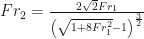
- From Fr1, determine the Froude number at the high part of the jump (Fr2.)
- Compute the flow through the jump, using the method described in “Getting the Jump on Hydraulic Jump.”
- If the Pitot tube is being used, perform the numerical integration to estimate the flow. You should also use this to compare with Fr2 computed from the jump calculations.
- Compare these flow results to the flow at the flow meter. It is a good idea to use the same units for your flow computation as appear on the flow meter.
- Compute the energy loss of the system.
- The velocity coming from the reservoir should be computed in two ways:
- Dividing the flow reading from the pump by the cross-sectional area of the upper reservoir outlet.
- Using the Fr1 and computing the velocity.
- Compare the velocities that result with the velocity computed by Equation (1).
What to include in the report
- A title page.
- Objective(s): What was the purpose of the experiment?
- Theory: Explain the theory behind this experiment. I expect you to be very thorough in what you cover in this section. You will need to refer to a fluid mechanics text concerning weir flow. Derive all equations used and label them appropriately. If you use any numerical integration or statistical analysis methods, discuss them.
- Observed Data: Put the observed (not calculated) data into tabular form; don’t forget units. Include a few sentences to orient the reader. You will need to include the Froude Number for both the upstream and downstream portions of the jump (which you’ll need anyway.)
- Results/Discussion: The report should include the following:
- A tabulation of both the upstream and downstream Froude numbers. It is totally unnecessary to put this result in a graph; if you had read the handout, you would know that
- A graphical and tabular comparison of the actual flow versus the flow calculated from the jump heights and Froude numbers. Use the units on the flow meter (GPM.)
- A tabulation of the power losses in the jump.
- Tabulation of the anticipated flow from Torricelli’s Law for both reservoir levels. Which level more corresponds with this law? Why?
- Some analysis of this data. For example, how well did the reference flow, hydraulic jump and numerical integration using the Pitot tube compare to each other? What were likely sources of error?
- Conclusions: Did you accomplish your objectives? In general, what did you learn from this lab? Do you have any recommendations for improving the experiment? Don’t skimp on this section; give it real thought and effort.
- References: Include any references you used. Be sure to cite them in the main text, and reference them using the format outlined in the lab report format document.
- Appendix: Include the “raw data” sheet here. Show any relevant sample calculations.
