
Fourth in the series of Fluid Mechanics Laboratory videos.
Scroll down for the procedure. More information on the subject:
- Background Material (important to understand the topic)
- Buoyancy and Stability: An Introduction (instructor’s handout)
- The Experimental Determination of the Metastatic Height. A textbook treatment (with worked example) of the experiment actually run.
- The Physics Behind “Rock the Boat”
- Helpful Material
- A Quick Overview of the CGS System. This is the best unit system to use with this and many other laboratory experiments.
- Know Your Own Ship
- Naval Ships’ Technical Manual Chapter 096: Weights and Stability
- The Propulsive Power of Screw Ships. Once you get them stable, ships have to go somewhere, and this is an investigation of how much power they take to do it.
- When the Pathfinder Gets Lost: some students like to “follow the lead” of someone else to get the course work done. That can have negative results other than those described in the syllabus, just like this example.
- My Special Interest in This Topic

The Procedure
What You’ll Need
The material referenced above is important background and we’ll be referring to it in the narrative below. You’ll need to download the Data Spreadsheet for the Experiment; it is designed to help you “fill in the blanks” and is not intended to assist you in calculations.
Objectives:
The objective of this experiment is to a) compare the displacement of the pontoon with its weight and b) compute the metastatic height of the experimental vessel in the three ways described in the theory section.
What is required in the report:
- Title Sheet
- Objective(s): What was the purpose of the experiment?
- Theory/Procedure: Include your interpretation of this section using the information provided in the handout. It is not necessary to repeat this word-for-word; you need to make a brief summary. Especially on the procedure detail how you performed the roll timing portion of the experiment.
- Observed Data: Put the data into tabular form, with units, when it is best to do so. Be sure to place an appropriate title caption above the table (see Lab Report Guidelines handout on Blackboard) and include a few sentences to orient the reader.
- Analysis/Discussion:
- You need to make an explicit comparison between the weight of the ship from the scale and the displacement of the ship, as described in Buoyancy and Stability: An Introduction (instructor’s handout). If you measured the ship in cm and weighed it in grams, that should be fairly simple: the weight of the displaced water is the volume of the water times the density of 1 g/cc3. From here you can make a direct comparison with the weight from the scale.
- Present and discuss the results of your stability measurements, using the three methods:
- For the theoretical instability calculation, show me a table of your dimensions and weight, and the GM that results. Be careful; the results of the moment of inertia method give you GB, not GM.
- For the weight shifting method, you will need to make clear how you shifted the weight, and how that affected the angle.
- For the roll timing experimental measurements, give at least three roll times you have taken. Are they consistent with each other? Why or why not? Are they consistent with the other two methods? Why or why not?
- Conclusions – What did you learn? Did you accomplish your objectives? How well did your experiment compare to the theoretical value of the instability point? Can you identify any limitations of this experiment? Do you have any recommendations?
- Appendix – Include the “raw data” sheets here. Also, provide a sample calculation for a complete data set from your experimental data.
- References – Include any references cited here.
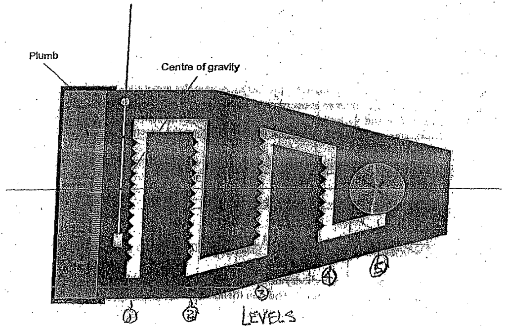
Apparatus
The arrangement of the apparatus is shown below. A rectangular pontoon floats in water and carries a plastic sail, with five rows of V-slots at equally spaced heights on the sail. The slot centers are spaced at 0.75 cm intervals, equally disposed about the sail center line. An adjustable weight, consisting of two machined cylinders which can be screwed together, fits into the V-slots on the sail. This weight can be used to change the height of the center of gravity and the list angle of the pontoon. The pontoon also includes two magnetic weights which should be placed in the bottom of the apparatus. A plumb bob is suspended from the top center of the sail and is used in conjunction with the scale fitted below the base of the sail to measure the angle of list.
You first need to follow the steps to determine the metastatic height of the ship using the analytical method. We will use the single level method, where you move the weight along the bottom row to determine the metastatic height.

Procedure:
Determine the Displacement and the Analytical Metastatic Height
- Weigh the main adjustable weight m and record this weight.1
- Affix the main adjustable weight to the sail at the lowest row of teeth with the screw at the centerline.2
- Place the two magnetic weights to the bottom of the ship, one on each side of the sail.
- Weigh this assembly and record the weight as M. Both variables m and M will become critical in The Experimental Determination of the Metastatic Height.
- Measure the beam, length and height of the hull using the provided ruler. Also be sure to account for the thickness of the hull, which can be measured using the provided micrometer. This will provide W and L for Equation (2) of Buoyancy and Stability: An Introduction. Measure these quantities in centimeters; using the CGS system will make the calculations much simpler.
- With all the weight in the vessel, place it in the water. Adjust the position of the magnetic weights so that the freeboard is uniform around the ship and the angle measurement is at zero degrees.
- Measure the freeboard of the vessel in centimeters, and from this compute the draught. The volume of the water displaced is given by Equation (2) of Buoyancy and Stability: An Introduction. Compare the weight of the displaced water to the weight you computed above. (The density of water is 1 g/cc, thus the displaced volume in cc is the same as the displaced weight in g.) Are they the same? Also, compute the location of the center of buoyancy, which is half the distance of the draught from either the bottom of the vessel or the water line.
- Use Equation (6) of Buoyancy and Stability: An Introduction to compute the distance between the metacenter and the center of buoyancy MB.
- The height of the center of gravity may be found as follows (see figure below):
- Move the two magnetic weights at the base of the pontoon so that the freeboard is uniform all around the hull.
- Fit the thick knotted cord, with the plumb weight, through the hole in the sail, ensuring that the plumb weight is free to hang down on the side of the sail with the scored center line.
- Clamp the adjustable weight into the V-slot on the centerline of the lowest row (Row 1, the drawing shows the highest row, but since we’re doing a single-level weight shift we’re using the lowest row only) and suspend the pontoon from the free end of the thick cord. Mark the point where the plumb line crosses the sail center line. Measure the distance from that point to the bottom of the boat.
- Compute the distance GB by subtracting the distance from the center of buoyancy to the bottom of the boat (in this case D/2) from the distance you just measured.
- Compute the analytical GM = MB – GB.
Experimental Value of GM by Shifting the Center of Gravity3
For more information about this, see The Experimental Determination of the Metastatic Height.
- Starting from the main adjustable weight at the centerline and the lowest row of teeth, move the weight in the right direction in 1.5 cm increments (two teeth,) recording the list angle of the ship at each point.
- Move the weight in the left direction in 1.5 cm increments, recording the list angle of the ship at each point. At this point your data collection should look like this, the first three columns should have the data:
| Right or Left Displacement xr or xl , cm | Right Angle θr, degrees | Left Angle θl, degrees | Total Angle θr + θl, degrees | tan(θr + θl) | GM from equation below4 |
| 1.5 | |||||
| 3.0 | |||||
| 4.5 | |||||
| 6.0 | |||||
| 7.5 |
- The distance of the metastatic height from the center of gravity can be determined for each displacement and corresponding angle by the equation (enter these results in the rightmost column above after computing the angle sum and tangent)

where
- m = mass of moving weight
- M = mass of entire ship with weight
- GM = distance from center of gravity to metastatic height
- You can take an average of the results to determine the final GM. Before you do you may want to apply Chauvenet’s Criterion from Experiment 2 to exclude outlier(s). IMPORTANT NOTE: if you use a spreadsheet to do these calculations (and you probably will,) keep in mind that spreadsheets require arguments for trigonometric functions (like tangents) to be in RADIANS, not degrees. You will have a disaster on your hands if you fail to do this.
- Compare this result to what you determined analytically. Make sure that you have subtracted the GB from the MB to obtain an analytical GM before you make any comparison (see Step 12 above.)
Rocking the Boat
This is a little more informal of a procedure. You’ll need to practice this a bit before taking data. You also need to look at The Physics Behind “Rock the Boat”.
- Return the weight in Row 1 at the centerline of the vessel.
- Move the ship to the large tank used by the hydraulic jump experiment. This will mitigate the effect of reflecting waves coming back and affecting the motion of the ship during rocking.
- Using a finger on the gunwale about midships (either side,) begin rocking the boat gently until you get a “rhythm” of rocking. Make sure water doesn’t come over the gunwale and enter the boat; this will ruin everything.
- Stop rocking with your finger on the gunwale with the gunwale close to the waterline. You may need to slow the boat down gradually to do this.
- Release the vessel completely. Record the time the vessel takes to complete one full roll (as defined above.)
- Use Equation (7) to solve for GM.
- (Optional) Compare the roll time to the rule of thumb regarding optimum roll times. Would a creature setting out to sea in this vessel have a comfortable voyage from a roll standpoint? How does this boat roll? Does this agree with your observation?
1 We will refer to the measurements you take as “weights.” Since they will be in kilograms or grams, they’re really masses. You could convert them to weights by multiplying them by the acceleration due to gravity, but this is additional math that really isn’t necessary. It’s easiest to compare masses to masses.
2 It is certainly possible to use any of the rows of teeth for this experiment. As a practical matter, the lower the row you use, the more data you will collect. However, once you’ve chosen a row of teeth, then it is essential for you to measure the center of gravity at the midships point of that row of teeth and not another! The midships point is any point along that light vertical groove in the sail.
3 The source of this method is Lewitt, E.H. (1923) Hydraulics and Fluid Mechanics. London: Sir Isaac Pitman and Sons. A worked example of this method is given on the instructor’s website.
4 Keep in mind that you’re pairing the two shift distances; for example, you’re pairing the shift distance to the left of 15 mm with the distance to the right of 15 mm, thus the total shift distance .
