James N. Warrington
Associate, American Society of Naval Engineers
Presented at the Annual Meeting, 22 December 1893
Reprinted in the Naval Engineers Journal, July 1983
Since the investigations of the elder Froude, friction and wave making have been fully recognized as the leading elements in the resistance of ships. The resistance due to eddies is known to be quite inconsiderable in modern ships, while the variations in resistance which accompany change in trim, bodily rise or subsidence of the vessel, and wave interference. all occur at such speeds as produce waves of great magnitude relative to the displacement. Within the limit of speed at which these phenomena appear, friction and wave making may be regarded as supplying substantially the entire resistance, and it is here essayed to formulate the propulsive power absorbed by these two elements of resistance with with such a degree of approximation as may be attained by attributing the properties of a trochoidal wave to the waves of a ship.
Friction
The horse-power of the frictional resistance may be expressed by the formula
in which represents the area of the wetted surface, the speed in knots, and a constant to be derived from the coefficient of friction. For a clean painted surface exceeding fifty feet on length Froude’s experiments show a resistance of 0.25 lb. per square foot at a speed of ten feet per second, and 1.83 as the power of the speed to which the resistance is proportional. From these quantities are decided the values and , the speed being expressed in knots of 6,080 feet and the wetted surface in square feet.
Wave Making
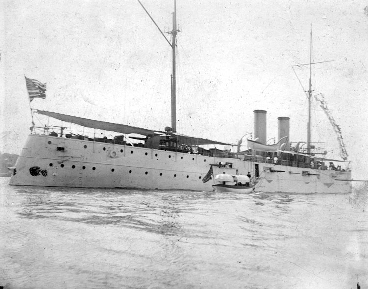
USS Cincinnati, New York, NY, June 1896.
Considering the wave generated by the ship in motion, it may be observed that similar ships produce similar waves, and that for a given ship the ratio of the magnitude of any series of waves to the magnitude of any other series, as for example of the bow waves to the stern waves, will be constant at all speeds so long as their generation is free from mutual interference. Moreover the wave of any series will retain their similarity at all speeds, for the orbital velocity as well as the speed of advance of the wave form must both be proportional to the speed of the ship.
The aggregate energy of all the wave of the ship may therefore be conceived to be embodied in a single series of representative waves having a speed of advance equal to the speed of the ship.
As the particles of water in the longitudinal stream lines approach the ship they meet the component stream lines diverging from the apex of the bow wave and follow the resultant stream lines around the ship. The velocity in the diverging stream lines must clearly be sufficient to impart the necessary transverse displacement during the time occupied in the passage from the bow to the midship section. The diverging stream-line velocity will then be proportional to , in which is the speed of the ship, is the area of the midship section, and the length of the combined entrance and run. But this diverging stream-line velocity is closely proportional to, if not identical with, the orbital velocity of the bow waves. Hence these orbital velocities will also be proportional to , and since the wave of each series grow in like proportion with increase of speed, the orbital velocity of the representative wave also will be proportional to the same ratio.
Assuming now that the waves of the ship possess the properties of trochoidal waves, it follows that the height of the representative wave will be proportional to , in which represents the wave length, the orbital velocity, and the speed of advance. Furthermore, the breadth of the wave will be proportional to its height, for as the height increases the orbital velocity increases throughout the entire breadth of the wave, and imparts its motion to more remote particles previously at rest.
The horse-power of a series of trochoidal waves, having a length , a height , and a breadth , is thus expressed by Mr. Albert W. Stahl, U.S. Navy:
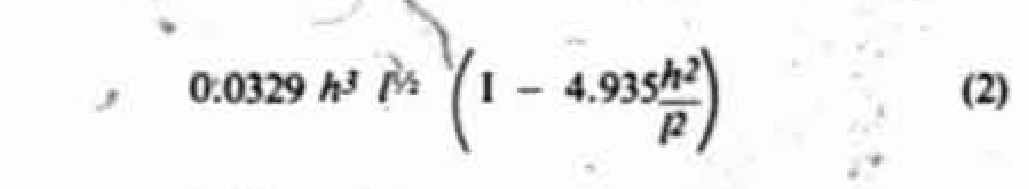
The ratio is constant for similar ships and for all speeds of a given ship, and is proportional to . Since with such a range in this latter ratio as may be found between a torpedo boat and an armored cruiser, the quantity in parenthesis would vary by a fraction of one percent, it may reasonably be neglected. The wave horse-power then becomes proportional to . But is proportional to , and h to , hence the horse-power absorbed in wave making may be expressed by the formula
in which is a constant to be derived from the performance of a model ship.
USS Montgomery, Tompkinsville (Staten Island), NY, June 1896
The imaginary representative wave is conceived as having a speed of advance equal to the speed of the ship, and in this respect is plainly in harmony with the transverse series. The speed of the advance of the diverging waves is dependent not only upon the speed of the ship but also upon the angle of divergence of their crest lines, and this angle of divergence is dependent upon the bluntness of the ship, or in other words upon the ratio , so long as the mode of distribution of the displacement remains the same. The length of the diverging waves will then vary with the ratio, and the effect will be that in the blunter ship the diverging series will absorb a greater amount of energy relative to the transverse series than in the ships of finer form. This relative increase in energy in the diverging series must, however, be accompanied by a corresponding diminution of the energy in the transverse series, for the total energy in both series is derived from the diverging component stream lines, the velocity of which is proportional to , and this total energy thus derived will be independent of the relative importance of the two waves. The condition necessary to the preceding statement is that the model ship, whence the constant is derived, and the projected ship shall be similar in cross section and identical in mode of distribution of the displacement. When this condition is fulfilled, therefore, the representative wave becomes a true measure of all the waves subject to the approximation involved in its trochoidal nature, and in the modification expression (2).
Concerning the limit of speed in the application of the formula, it should be observed that each wave-making feature is assumed to generate its appropriate wave without interference; hence the beginning of each interference marks the limit of its applicability.
At corresponding speeds the power absorbed in wave making becomes proportional to the square root of the seventh power of the scale of comparison, as should be expected.
The Wake Current
The sum of and is the effective horse-power required to tow the ship. When propulsion is effected by a screw propeller at the stern, other varying elements are introduced. The following current, by delivering momentum to the propeller, restores a portion of the energy already expended in overcoming the frictional and wave-making resistances.
The Pathfinder
Let represent the speed of the ship, the mean speed of the following current, and the diameter of the propeller. Then the energy imparted to the propeller per unit of time by the following current will be proportional to
but assuming a constant percentage of real slip, is proportional to
which being substituted in (4) reduces the increment of energy to the form
The following current has three components of independent origin, viz: the frictional wake, the orbital velocity of the stern wave, and the orbital velocity of the recurring transverse bow wave. It has been shown that when the waves of the bow series interfere with the formation of the stern wave the limit to the application of this analysis has been reached. Therefore the effect of the bow wave need not be considered.
The speed of the frictional wake will here be regarded as proportional to the speed of the ship; hence the energy derived from it, being a constant proportion of the total power, need not be considered here.
Still attributing the properties of the trochoidal wave to the waves of the ship, the orbital velocity of the stern wave at the center of the propeller will be proportional to
in which is the length of the after boddy, the modulus of the hyperbolic system of logarithms, the depth of immersion of the axis of the propeller, and a constant such that equals the wave length.
Substituting (6) for in expression (5) the increment of energy becomes
The value of constant as derived from the results of the experiment of Mr. George A. Calvert is ; but this value should be regarded as provisional, since like depends upon the mode of distribution of the displacement.
Summary
Let represent the total effective horse-power required at the propeller. Then
and are constants, depending upon the form of the ship, having a provisional value of 1.66.
Analysis of Power
If from the indicated horsepower, the power required to overcome the constant resistance of the unloaded engine is deducted, the result will be the new horse-power applied to the propulsion; the the ratio of to this net horse-power will represent the combined efficiency of the mechanism of the engine so far as the variable friction is involved, and of the propeller, including the effect of the frictional wake and of the augmentation of resistance by the propeller. These latter two effects are thus assumed proportional to the power applied. The ratio may then be expected to remain constant so long as the propeller efficiency remains constant.
Applications
U.S.S. Bancroft
The results of the progressive trial of the U.S.S. Bancroft given by Passed Assistant Engineer Robert S. Griffin, U.S. Navy, suffice for determination of the value of the constant of the vessel. The Bancroft is a twin-screw practice ship of the following dimensions: length of immersed body ft.; displacement on trial tons; area of immersed midship section on trial sq.ft.; wetted surface on trial sq.ft.
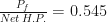
Having calculated the power absorbed by surface friction on the basis of Froude’s coefficient and exponent, and also the value of the factor involving the following current, the constant is given such a value as will maintain the ratio approximately constant. The value of thus found is for the Bancroft 329, and ratio . The resistance of the unloaded engine is assumed at 2 lbs. per square inch of the area of the low-pressure pistons. Using these values, the power at the several speeds hsa been calculated and is given in Table I, where the observed powers are also given show the degree of approximation.
In order to illustrate the scope of the formula the ratio is given in Table II together with explanatory data for each of seven vessels, five of them being twin-screw ships of the U.S. Navy, and the two others the S.S. Umbria of the Cunard line and the torpedo boat Sunderland, built by Messrs. William Doxford and Sons, Sunderland, England. With the exception of the Umbria these vessels may be regarded as approximations to the form of least resistance in smooth water. The Umbria has a quasi-parallel middle body, the length of which has been approximated by ascribing to the combined entrance and run a prismatic coefficient of fineness of 0.56. Table III contains the results of the progressive trial of the Umbria together with the calculated power. The same comparison is shown in Figure I.
In making these calculations, the constants of the Bancroft have been employed, their values being . If should be stated that the application of this value of to all of these vessels is not strictly warranted, for they are undoubtedly dissimilar in cross section and also in mode of distribution of displacement. Nevertheless it is assumed that they possess a sufficient degree of similarity to serve the purpose of illustration.
The resistance of the unloaded engine is based on two pounds per square inch of the area of the low-pressure pistons in all cases. The length is the combined length of entrance and run, being the length of the immersed body in all cases except the Umbria. The ratio given as an index to the character of the ship form a propulsive point of view. If all these vessels possessed the required degree of similarity, and had propellers and engines of equal mechanical efficiency, the ratio should be the same for all, provided the speeds were within the limit indicated.
Limit of Speed
Since the formula gives only the power absorbed in surface friction and in waves generated without interference, it is obvious that it may be used as a measure of the total power only when these elements constitute the entire resistance. The earliest departure from the condition of applicability may be expected to accompany an interference by the recurring transverse bow wave in the generation of the stern wave. Since the relative magnitude of the bow and stern waves is dependent upon the form of the ship, it is clearly impossible to formulate generally the limit at which such an interference will occur. The limit must therefore be found form the performance of the model ship whence the constants in any case are derived.
The U.S.S. Bancroft, within a speed of 14.52 knots, gives no evidence of the limit, as may be seen by reference to Table I. At this speed .
The S.S. Umbria gives no indication of the limit within the speed of 20 knots, as may be seen by Table III or Fig. I. At 20 knots length of ship.
On the other hand, the progressive trial of the torpedo boat Sunderland affords a convenient illustration of the inapplicability of the formula. Figure 2 shows the power curves, both actual and calculated.
At the speed of 14 knots the value of the ratio is such as to warrant the conclusion that at this speed the formula gives the power with sufficient accuracy. A glance at the curves, however, shows that this cannot be said of any higher speed until 20 knots is approached. Fourteen knots may then be regarded as the limit of speed at which the formula may be applied. At this speed . Beyond this speed the familar hump appears. It may be of interest to note that the curves intersect again in the region of 20 knots, at which .
It is not intended to question the existence of minor humps at speeds below the limits here noticed, but simply to observe that in the published curves of the Bancroft and Umbria they are not appreciable. It is possible that such humps may be partially neutralized by the action of a simultaneous increase in the wake current upon the propeller. In any event, their existence must affect the accuracy of the calculated power, although commonly to such as slight extent as to be inappreciable.
Since the magnitude of the waves of the ship varies with the ratio it follows that both the size of the hump and the speed at which it appears will be influenced by this ratio.
Conclusion
The method of this analysis may be summarized thus: The resistance of ships is so largely due to surface friction and wave making that all other forms may be neglected except at very high speeds. Within the limit of speed at which interference occurs in the generation of waves, the formula (eq. 8) enables the power absorbed by these two principal elements to be computed, provided the constants and have been experimentally determined by means of a model ship having the same mode of distribution of displacement as the projected ship. The ratio of the power thus computed to the net power of the engine is constant so long as the propeller efficiency is constant. Finally, the indicated horse power may be obtained by adding to the net power the power absorbed in the constant resistance of the engine.


 but assuming a constant percentage of real slip,
 which being substituted in (4) reduces the increment of energy to the form
 The following current has three components of independent origin, viz: the frictional wake, the orbital velocity of the stern wave, and the orbital velocity of the recurring transverse bow wave. It has been shown that when the waves of the bow series interfere with the formation of the stern wave the limit to the application of this analysis has been reached. Therefore the effect of the bow wave need not be considered.
 in which


 The value of constant


 In making these calculations, the constants of the Bancroft have been employed, their values being


 At the speed of 14 knots the value of the ratio


